Friday 29 May 2015

Printing the chopper's fuel tank

My good friend managed to print the fuel tank for the chopper bike project and it turned out pretty good. He has a home built version of Prusa printer and he's using my project to calibrate the fine tune the printer.

The CAD part was split in half to assist the printing process. There is still some finishing to do on the parts, using filler putty and sanding all the printing lines.

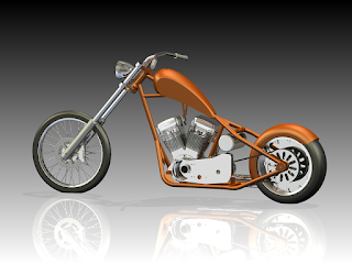
For those who don't remember what is the part for, here is a reminder of the project.


And the printed parts as received from the 3D printer.


Wednesday 13 May 2015

Back on track

As my left hand is healing nicely, I can now focus again on my scale modeling projects. In this post I am showing the progress on the Harley Davidson custom chopper project. As you know already, this is going to be scratch built, with only the rubber tires taken from a Revell 1:12 motorcycle kit.

As the central piece of any chopper is the engine, the first thing I want to clear from the table is making the engine parts. Luckily, one of my friend has just build a Prusa 3D printer and he was kind enough to do a test print for me. Since we're both beginners in this area, we tried to print the engine as one part. Unfortunately the results are not satisfactory, mainly due to parts orientation. So for the next test print we will take each part and print them separately. There are 8 main printable parts on the motor.


Below pictures show the first printed motor.


Eventually, the cylinder heads will be printed using a commercial printing service, as it would require a different technology like SLS to achieve the right quality.

A little distraction from motorcycle modelling

As I mentioned briefly in my previous post, I have fancied entering the scale model trains hobby. I am trying to resist the temptation as it will detract me from the current projects, but as a scale modeler, building a locomotive from scratch is an irresistible challenge. I am looking into non-running, HO scale trains.

After searching the web for some locomotive plans I found an excellent 3D model of LBSC Ayesha II. It was modeled in 61 mm gauge, while I am looking to build it in 16.5 mm gauge (HO scale). I know that the real locomotive only existed as a garden train (used in fun train parks in UK), but due to 3D plans availability, it is an ideal beginner's project.


As I normally do, I started with the 3D design in Inventor. The scale model will be a static one, without motors or working boiler. The challenge of the design process is that you cannot simply scale each part down to HO scale, but need to redesign each relevant part from scratch, in order to adapt it to the manufacturing tools I have available (mainly Sherline lathe and mill).

I spent two days to get to the current stage you see below. Pretty good progress if you ask me.


This is a non-committing project for me, as I will only work on it as time permits. 

Thursday 7 May 2015

A break from modelling

Hi,

In the last 3 months I was away from modelling due to a motorcycle accident I had in mid Feb. Luckily I got rid with only a broken hand which is currently healing nicely. I am planning to get back to modelling and have some updates to post soon.

In the meantime I was contemplating the idea of 3D designing and building a static HO locomotive. I am trying to resist the urge because I need to focus on the bike projects (Yamaha Roadstart and the custom cruiser).

Thanks for your patience

Wednesday 4 February 2015

Primary drive pulley

Today, I got my motivation back and did some more work on the Yamaha Roadstar project. I received some time back the micro belts from SDP. They are a perfect fit, having the same width and pitch as the original kit part.


This is the original kit part - it is molded as one single part with the belt and final drive pulley, requiring painting in different colors to achieve some sort of realistic look. So I decided to make them as separate parts. I have machined the primary drive pulley out of 6061 aluminum. It was not necessary but I wanted to do it anyway, as a learning process. I will have to do it on the custom chopper so better practice with every occasion.

I had to grind a special grooving lathe tool for this job, but since I am planning to do more custom bikes in the future, I will use it more than once. This was the first time I have attempted to grind such a tool and I am very happy how it turned out.


Unlike the kit part, which is supposed to be painted and glued, the machined part will be secured with a micro bolt and nut. So next job is to machine a 2 mm bolt with nut.

Some more photos of the pulley and fit:


Friday 14 November 2014

Miniature belt drive

These days I have been working on the designing the final drive assembly for the custom chopper scale model. Initially I planned to use a miniature chain drive, by using a kit from Top Studio (see details in an older post). But while working on Tamiya's Yamaha Roadstar kit, I found out that you can buy miniature belts in various sizes, the smallest one being 3 mm width with 1 mm pitch. They are designed mainly for robotics but would look good on the scale models as well. Check out at SDP-SI for their belts offering.

So with this idea in mind, I changed the CAD project to use a belt final drive. I am going to use the 3 mm width x 1 mm pitch belt and will design the pulleys so the belt length matches the models sold by SDP-SI.

One issue that surfaced when I added the belt and pulleys in the assembly was the clearance between frame and tire; the belt and pulley was rubbing both the frame and tire. I had to widen the frame rear to accommodate the new final drive assembly. It doesn't look so sleek as before but is not bad either. The rear fender will have a cut-off for clearing the belt, but I will not model it in Inventor.

One of the advantages of designing the scale model in a CAD software is that you can find such problems early. When working with metal you need to be precise because unlike plastic, once a part is cut it cannot be adjusted too much.


Wednesday 15 October 2014

Brake disks for the Yamaha Roadstar project - Part 2

Finally, the brake disks for the Roadstar are completed. It took me two attempts to do them, since I broke a 0.6 mm drill in and couldn't get it out, so I had to scrap the part and start again. The process of making them was as following:

  • Installed some aluminum bar stock on the lathe and turned down few mm, to get to the 25 mm required diameter. The plan was to make both disks at once, so I took into account the desired brake disk's and the cut-off blade's thickness
  • After that I removed the chuck from the lathe, with the bar stock still in, and mounted it on the rotary table, on the mill. Careful adjustments have to be made to align the spindle to the center of the brake disk. Then I started drilling the holes. I chose a simple pattern only with holes, in order to make it easier to fabricate. Basically there are five 4 mm radial holes, one 4 mm center hole (for the hub), five 0.5 mm radial holes for the bolts and forty-eight 0.6 mm cooling holes. Drilling the micro holes is tricky as the drills can easily break (which happened once) so I had to take my time. Also to make both disks at once, I had to drill deeper holes (around 2-3 mm), which is not really possible with such small drills (they snap easily). So in the end I had to do the disks separately
  • After the holes were drilled, I mounted the chuck back on the lathe and cut a 0.8 mm "slice" from the bar. The 0.1 mm extra is needed for the finishing job, since the cut-off will leave a rough surface
  • I then mounted the disk on the Dremel and polished the disk with 180 grit sandpaper, reducing the thickness to 0.7 mm


The disks should attach to the wheel hubs with 0.5 mm micro bolts; I intend to buy some from Scale Hardware.

All in all I am content how they turned out. Some photos below.