Showing posts with label 1/12th Scale Harley Davidson Chopper. Show all posts

Friday, 29 May 2015

Printing the chopper's fuel tank

My good friend managed to print the fuel tank for the chopper bike project and it turned out pretty good. He has a home built version of Prusa printer and he's using my project to calibrate the fine tune the printer.

The CAD part was split in half to assist the printing process. There is still some finishing to do on the parts, using filler putty and sanding all the printing lines.

For those who don't remember what is the part for, here is a reminder of the project.


And the printed parts as received from the 3D printer.


Wednesday, 13 May 2015

Back on track

As my left hand is healing nicely, I can now focus again on my scale modeling projects. In this post I am showing the progress on the Harley Davidson custom chopper project. As you know already, this is going to be scratch built, with only the rubber tires taken from a Revell 1:12 motorcycle kit.

As the central piece of any chopper is the engine, the first thing I want to clear from the table is making the engine parts. Luckily, one of my friend has just build a Prusa 3D printer and he was kind enough to do a test print for me. Since we're both beginners in this area, we tried to print the engine as one part. Unfortunately the results are not satisfactory, mainly due to parts orientation. So for the next test print we will take each part and print them separately. There are 8 main printable parts on the motor.


Below pictures show the first printed motor.


Eventually, the cylinder heads will be printed using a commercial printing service, as it would require a different technology like SLS to achieve the right quality.

Friday, 14 November 2014

Miniature belt drive

These days I have been working on the designing the final drive assembly for the custom chopper scale model. Initially I planned to use a miniature chain drive, by using a kit from Top Studio (see details in an older post). But while working on Tamiya's Yamaha Roadstar kit, I found out that you can buy miniature belts in various sizes, the smallest one being 3 mm width with 1 mm pitch. They are designed mainly for robotics but would look good on the scale models as well. Check out at SDP-SI for their belts offering.

So with this idea in mind, I changed the CAD project to use a belt final drive. I am going to use the 3 mm width x 1 mm pitch belt and will design the pulleys so the belt length matches the models sold by SDP-SI.

One issue that surfaced when I added the belt and pulleys in the assembly was the clearance between frame and tire; the belt and pulley was rubbing both the frame and tire. I had to widen the frame rear to accommodate the new final drive assembly. It doesn't look so sleek as before but is not bad either. The rear fender will have a cut-off for clearing the belt, but I will not model it in Inventor.

One of the advantages of designing the scale model in a CAD software is that you can find such problems early. When working with metal you need to be precise because unlike plastic, once a part is cut it cannot be adjusted too much.


Wednesday, 4 June 2014

Chopper Renderings

Yesterday, I did some refinements of the fuel tank shape and tried my hand on rendering the bike. Didn't have the patience to setup the lighting, just wanted to get it done fast.


Tuesday, 3 June 2014

Some updates

Due to a long business trip, the progress on the bike was slow. But since the last update I still managed to design the front brake caliper, headlight, handlebars and the fuel tank.

Thinking how I will make these parts, I suppose the tank can be made easier with modeling putty or even 3D printing, the headlight on the lathe (or use the plastic part from a Revell kit) and brake caliper again using 3D printing.

Still have to design the mounts for the fuel tank and the gas cap.


Sunday, 27 April 2014

Rolling Chassis and bending miniature tubes

Today I am going back in time with the chopper project and I want to show you the 3D model of the rolling chassis and share some thoughts about the fabrication process of the frame.


As you can see in the photos, the rolling chassis is almost ready from design point of view. The remaining things to add is the top motor mount, the forward control mounts and rear brake mounts. The fender was redesigned in Inventor and now it includes mount holes to attach it to the frame. The fender clears the rear wheel at 1 mm and I am planning to use 0.5 x2 mm miniature hex bolts from Scale Hardware to attach it to the frame. The bolt head is only 0.46 mm in height so it should clear the wheel.

Back to the frame, it will be made mainly in 3 mm brass tube and the sections will be silver soldered together. All the bends have a 10 mm radius and to bend the tubes I started building a miniature tube bender. Fortunately, I found a nice CAD plan on the internet and only had to adjust the dimensions, use nuts & bolts I have around and remove some parts that I feel I don't need.


With the Inventor parts exported to CAD format, I went to a local water jet cutting workshop and they cut the basic shapes in no time (it took them 7 mins to cut all the parts). Unfortunately I found that due to the small dimension of the parts, the accuracy of the cut pieces is not that good. The water jet leaves a rough and uneven edge, which has to be milled or filed flat. This will reduce the dimension of the finished part with about 0.2 - 0.3 mm on each edge. So I had to enter the new dimensions in the Inventor solid model to get the actual size. So do take into account this aspect if you plan to use water jet cutting on small parts - you may need to rescale the parts a bit. However, the benefit in time is worth it.

Now it's time to finish the parts...


Wednesday, 23 April 2014

Chain drive design

It's time for the final drive design. For this project, I decided to use a roller chain instead of the "traditional" belt drive. I intend to use a 1/12 scale chain & sprockets kit from Top Studio, even though they are designed for Moto GP bike kits from Tamiya or Fujimi. But before ordering such a kit I need to design a sort of a mock chain and sprockets, just to assess the frame width and wheel/fender clearances.

After few days of gathering information and learning about chains mathematics (e.g. calculate the number of teeths, sprocket diameters), I finally managed to finalize the design and dimensions. I don't intend to have accurate sprocket ratio or pitch, just to have something to help getting the clearances right.

Just to give you an idea of the scale, here are the chain and sprockets data I came up with:
Pitch = 0.955 mm
Roller diameter = 0.5 mm
Roller width = 0.6 mm
Sprockets thickness = 0.5 mm
Driver sprocket outside diameter = 6 mm
Number of teeth on the transmission side sprocket = 18
Driven sprocket outside diameter = 18.843 mm
Number of teeth on the wheel side sprocket = 60

Of course these will change once I get the Top Studio chain kit, but it was a good learning exercise on how to design a chain and sprockets in Inventor. Plus that due to this exercise I discovered that the primary transmission plate has to be adjusted a bit to clear the chain. Also the oil tank's diameter had to be reduced from 13 mm to 12 mm, to clear the transmission plate. The rear fender will have a cut off on the left side, but I will not model that on the virtual model but do it directly on the fender part.

Later I will have to decide how to attach the sprocket on the transmission axle - I would like to be able to turn the rear wheel and both sprockets on the final/real scale model.

Here are some photos:


Wednesday, 16 April 2014

An introduction to the current project

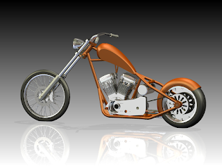
The main project I am working currently is to design and build a 1/12 scale custom chopper motorcycle. I intend to build almost all the parts, with few exceptions being the tires, which are taken from a Revell motorcycle kit. The engine and gearbox will probably be 3D printed as is too intricate and complex to use conventional methods like milling. The 3D printed part will be used as a master pattern and they will be cast in resin. All the other parts will be made in metal, mainly brass and aluminum.

I have started this project approximately one year ago, working slowly on the design. Since it's an ambitious and complex project, I decided I will do the design in a CAD tool first and only then start building the physical parts. So I started learning various CAD tools and designing the bike in parallel. Actually the bike was the main motivator to learn the CAD tools as they are quite complex and have had no previous training in this domain.

Here are some photos of the current design